|
The Base:
Drilling the first holes in the base. |
 |
|
|
|
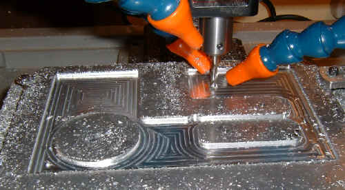
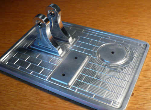
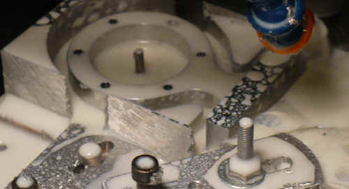
| Spiral pocketing the base to leave little pedestals for
the cylinder mount, crankshaft mounts, and fuel tank mount. This is my
own variation on the original slab from the original design.
I was still using a vacuum system here. I've since changed to flood coolant. |
 |
|
|
|
|
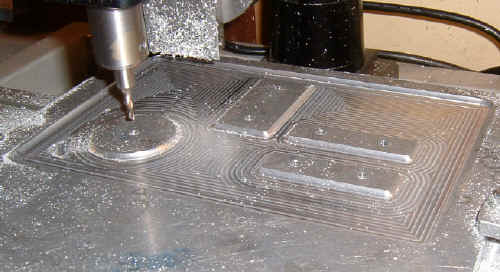
Spiral pocket complete |
 |
|
|
|
|
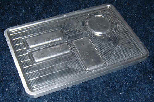
Almost cut free from the background |
 |
|
|
|
|
Other than some sanding and polishing, the base is mostly complete. Final finish yet to be determined. The base dimensions are 8.00" x 5.75" x .375" |
 |
|
|
|
| Crankshaft bearing brackets - 2.50" high x 2.00 wide. The design calls for a one piece bracket and was rather plain looking. I designed these instead. Nicely polished but will likely be anodized once I figure out a colour scheme. (The lines that you see across the brackets are just the reflection of the oak desk that they're sitting on.) |  |
|
|
|
|
Crankshaft bearing brackets temporarily in their final home. |
 |
|
|
|
|
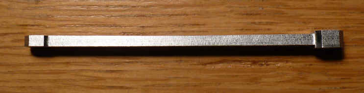
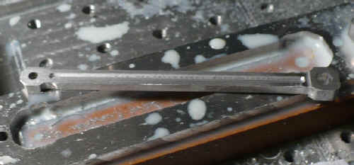
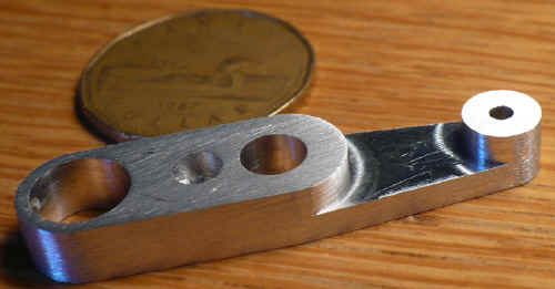
This is the connecting rod. About 3.3438" x .3125" x .1875" |
|
|
|
|
|
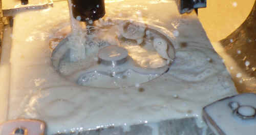
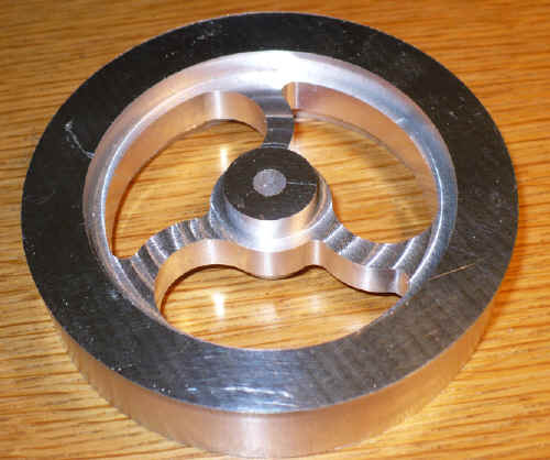
The Flywheel started out as a piece of .875" scrap yard aluminum Bubble, bubble, toil & trouble... |
|
|
|
|
| Almost done. Next job is to mill out the exterior. Then, I'll clean it up on the lathe and turn to final dimension. The flood coolant and A2ZCNC Zero Backlash upgrade combine to give a very fine finish. | 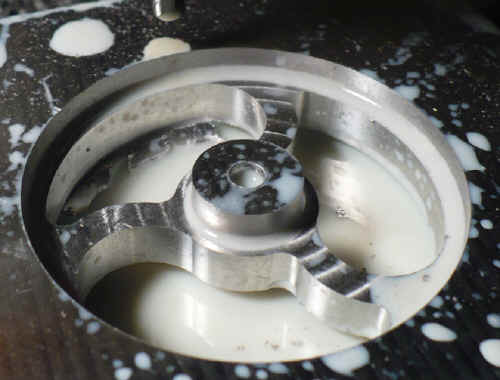 |
|
|
|
|
Next stop, the lathe |
 |
|
|
|
|
The Crank Arm after its first wet sanding. |
 |
|
|
|
|
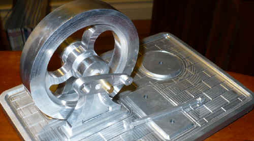
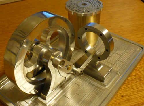
Starting to come together |
 |
|
|
|
| Rather than using the brass door knob for a fuel tank as suggested in the plan, I made my own. A bit too tall still here, I'll probably cut the height down about .75" or so. The lid will be fastened down by 4-40 machine screws and the center hole will be for filling the tank. A bit small perhaps but there's room to open it up a bit. | 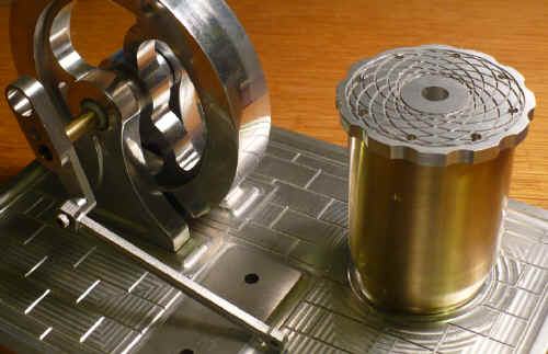 |
|
|
|
|
The Cylinder Pedestal in progress |
 |
|
|
|
|
Finished Cylinder Pedestal. |
 |
|
|
|
|
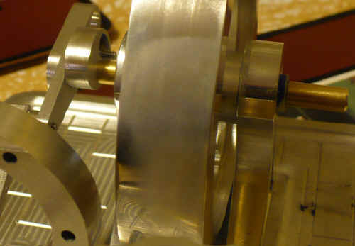
The new "high performance" cam. The slot
allows |
 |
|
|
|
|
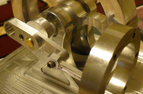
The cam now mounted to the back of the crank
arm. The #4-40 socket head machine screw to the left of the |
 |
|
|
|
|
The other side of the crank arm with the cam in full
view. |
 |
|
|
|
|
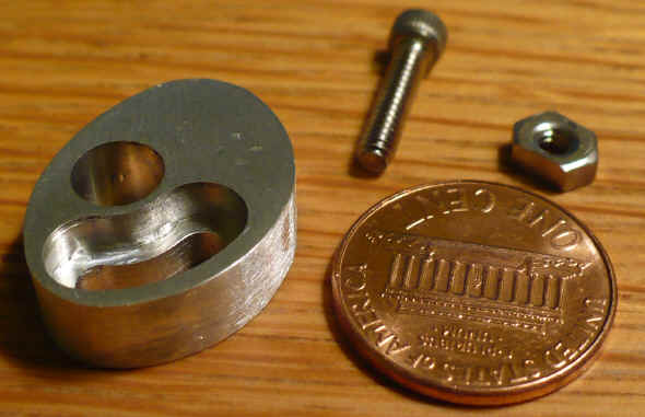
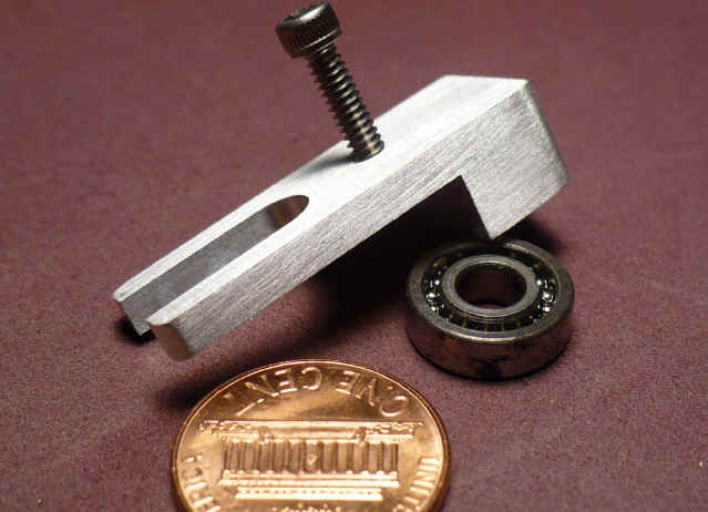
The Cam Roller Fork.
I made the Crankshaft Bearing Brackets above from .375" stock instead of .250" before I really looked at the rest of the drawings. As a result, I had to make a bit of a change on this piece. It's .250" longer which means the only other changes are to the compression spring and the pushrod which will also be shortened by .250" I need to make a sleeve to cover over the machine screw with an OD the same as the ID of the ball bearing also shown here. |
 |
|
|
|
|
With the bearing in place. It was hard to believe but I actually had the correct bearing in a box of stuff that I bought from a neighbour a couple of years ago. The neighbour's name? Burns ! (Thanks Jim). A prophetic coincidence for a Fire Eater Engine. |
 |
|
|
|
|
Updated: September 04, 2008 |
|