|
|
||||||
|
||||||
|
|
||||||
|
- I was also advised that the D.P. of 10.35 on two of the gear was wrong. - Gary emailed me the following : " I think the main issue with the clock was I was too efficient in adding the little push the pendulum needs to keep running.As the weights fall they are stopped by the escapement mechanism.The entire gear train comes to a complete stop and starts up again when the pendulum retraces its path. The way the escape part is shaped ends up giving the pendulum a very small push to keep it running. If you didn't do this the pendulum would eventually stop due to friction and wind resistance.
- And finally, Gary advised that he never made the clock. That in
itself if not necessarily a bad thing as it should not affect the design
which I find is beautiful and should not stop anyone from making
one for themselves. But I think it is a material issue and prospective
builders should know this. I have recently (2016) built two of Clayton Boyer's clocks. The first one, Simplicity was a great learning exercise and runs ok. If I built it again, now being a bit more experienced, I'm sure that it would run like a top. The second one, Solaris, runs beautifully and is gorgeous. Whether you cut your parts manually or with CNC, you will spend many hours of your own time in a clock project. While the appeal of free plans of Gary's clock may be appealling to some, I very strongly suggest that you pay a few dollars to Clayton Boyer, Brian Law or Wooden Times. They all make beautiful designs, their designs run and are well tested, and there are many people who have built clocks from their plans. The designers are very engaged with builders to assist when necessary. The broad base of builders of these clocks give the new builder a vast collection of experience ready to be passed along. Finally, go to Youtube and search on these names to see many running examples. |
||||||
|
This is my first real CNC project so a few parts have been cut and then
re-cut. Here's the results so far...
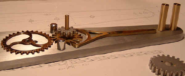
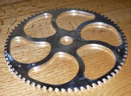
"Junk Yard Cogs" refers to my shopping habits. Almost 100% of the parts below are made from junk yard scrap. I found these plans on the internet. It's a skeleton clock and was actually designed to be made of wood. Everything so far is brass and aluminum. The thick parts being aluminum and the thin stuff in brass. I hope my efforts will do justice to this beautiful design. Making this clock takes a huge amount of time. For example, a 3'" x .250" gear takes about 5 hours to make. Between fine tuning the DXF drawing and setting the cut path in the CAM software, and then the actual cutting and finishing, it's a very long process. Starting this from scratch, without a drawing or CAD file would be a career in itself I'm sure. Gary deserves a great deal of thanks for posting his plans in DXF
format without charge. The satisfaction in completing each part is
absolutely immeasurable. THANK YOU Gary. Gary's site seems to be missing in action. He gave his plans aware as a free download. Since I got mine free, and since I've been asked by others for copies, I will post them here for download just as Gary did.
Plans no longer available from this site. |
Unauthorized Photo courtesy of Gary, the clock master. |
|||||
|
|
||||||
| This gear is about 2" in diameter. The largest one will be a bit over 7" which is just within the limits of my Sherline CNC mill. |
|
|||||
|
|
||||||
|
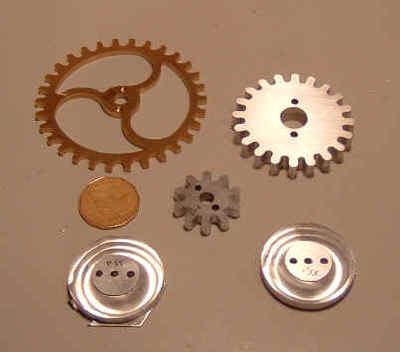
Some of the finished gears. The Loonie is in the picture to provide a
sense of scale. For you non-Canadians, a Loonie is about 1.125"
The extra two holes on either side of the centre hoe in all of these pieces is so I can mount the part in a mandrel and mount them in my lathe chuck and also so I can attach the gears to the shafts with machine screws instead of glue as called for in the plans. |
|
|||||
|
|
||||||
|
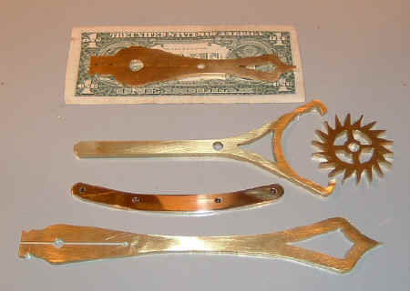
More of the brass and a $US which helps some of you get a better sense of size. Only one piece has been tumbled and polished so far. |
|
|||||
|
|
||||||
|
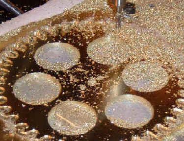
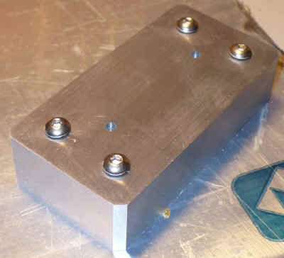
This is the base to which all of the shafts, gears, etc will be
attached. After proving to myself that I could indeed cut some of the
more intricate parts, I thought it was time to make the base so I'd have
a place to attach things and to test those parts for fit and accuracy.
The base is actually a refugee from a scrap yard. I found a piece of 1/2" aluminum plate a bit over 30" wide. Since the plate is 29" long and way too big for my little Sherline mill, I had the local water jet cutter whip it into shape for me (and a spare just in case). He also pierced the hole locations. $60 and worth every penny. |

You can't really tell from the picture, but it's been carefully wet-sanded. And, I beveled the edge with a 15 degree router bit. I may get another bit and push it closer to 30 degrees. I'm thinking of engine turning the face but it may detract from the rest of the mechanical parts which are really the start of the show. The brushed look from sanding looks quite nice. |
|||||
|
|
||||||
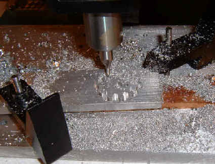
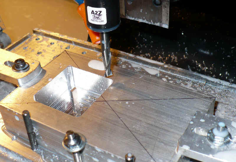
| With great care and a quick practice run, I milled the first hole recess. Good thing to as I was not properly setup for the first one and all the work so far would have been for naught if I blindly let the mill do it's thing. This will be the most time consuming piece as any mis-steps on the face of it will turn it back into scrap metal. ( I do have a contingency plan in mind though - larger diameter shaft bases.) |
|
|||||
|
|
||||||
|
The parts are starting to be fitted to the base. Now
it's easier to figure out what needs a bit of re-engineering. |
||||||
|
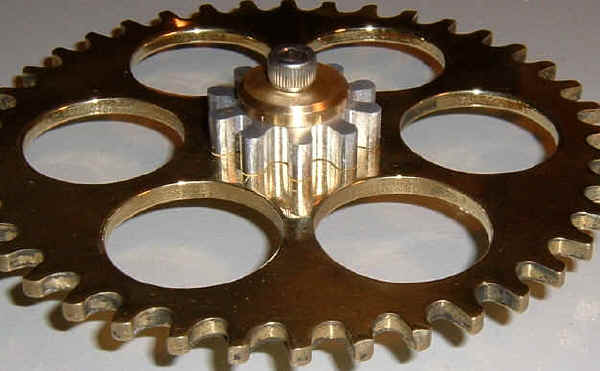
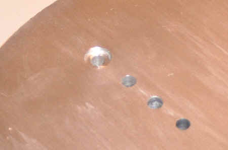
P19 wheel I've changed this a bit. The plan called for a different decorative hole pattern ( at least I hope it was just decorative). The original holes came too close to the center hole for my needs. I needed to drill two additional holes - one on either side of center. These are 1/8" each. See the next photo. |
|
|||||
|
|
||||||
|
P19 wheel above The plan called for the 40 tooth wheel and the 10 tooth pinion to be glued together. I didn't want to do that. So, I drilled two additional holes, 1/8" diameter, 1/4" on either side of the center in each gear. Then, I inserted a piece of 1/8" aluminum rod into each and trimmed to length. They don't need to be glued or screwed into place as they get sandwiched between the back side of the shaft and the washer and socket screw on the front. This locks them together quite nicely. See next photo. |

|
|||||
|
|
||||||
|
Instead of a tapered pin to hold it all together, I cheated. I made a brass washer which was actually one of the brass pieces cut out of one of the holes on the large wheel shown here. I then drilled and tapped the shaft that the gears spin on and turned it to length so that when the socket head screw is tightened, the wheels still run free but with little or no slop to them. I'll be getting some nice stainless steel button head socket screws to replace the one show here. That should help to finish things off with a little dressier finish. |
||||||
|
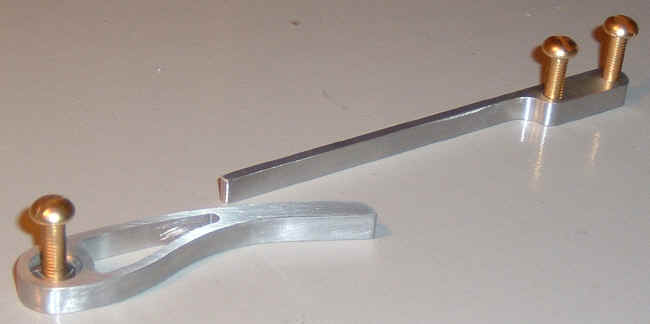
I'm still experimenting with the attaching hardware. You can see the S/S
button head socket machine screw The brass washer is one I made for another part of the clock; it's
just here to check for appearances and fit. |
||||||
|
The weight pulleys. |

P36 Pulleys for weights (4.50" diameter) |
|||||
|
|
||||||
|
P31 3.125" Ratchet Wheel |

|
|||||
|
|
||||||
|
P33 Ratchet Striker (3.028" long) |
||||||
|
P43 Pinion (1") and P48 wheel (3.2") |
||||||
|
P22 Pinion and P23 Wheel |
||||||
|
Progress to August 20,2006 |
||||||

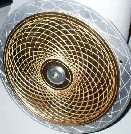
P53 Pendulum Top Disc |
||||||

P53 Pendulum Top Disc |
||||||
P57 Pendulum Weight - in progress CNC is faster than doing the machining manually but this little
1.625" x 1.75" x 0.750" pocket took 1.5 hours |
||||||

|
|
|||||
|
P57 Pendulum Weight Finished except filling with lead for prescribed weight of about 6 Lbs. |
||||||

P54a Lower Pendulum Disc |
||||||

P54a Lower Pendulum Disc - The back side view |
||||||

P54a Lower Pendulum Disc - The front view |
||||||
|
P54b Lower Pendulum Disc
This is the brass face for the pendulum disc. It's made from
|
|
|||||
|
|
||||||
|
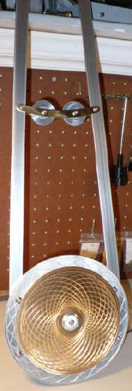
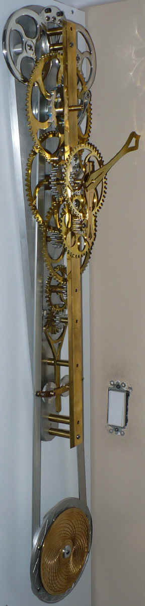
The Pendulum Assembly Overall length - 41 inches Left: Quickly assembled to test fit... which was perfect ! Right: Final assembly |
|
|||||
|
|
||||||

P32 72 tooth wheel in aluminum - in progress |
P32 finished. About 7.5" diameter. |
|||||
|
|
||||||

A12 Drawing Assembly |
||||||
|
|
||||||

|

|
|||||
|
This is what happens when you make this clock from metal and not wood.
All the connections need to be mechanical, not glued. This is the P30 Ratchet Shaft being drilled to connect it to the P31 Ratchet Wheel |
||||||
|
|
||||||

Fully assembled and ready to mount on the base |
||||||
|
|
||||||

P 26 Cannon Tube tapping with #4 tap |

|
|||||
|
|
||||||

P 28 Hour Hand attached to Cannon Tube |

Every now & then something doesn't go quite right. I drilled a .375" shaft hole a wee bit off center. The only solution seemed to be to open up the hole and put in a separate piece to support the shaft. But it had to look like I did it on purpose. Which of course... I did. So the .375" hole was opened up to .500" and two #10 machine screw holes were drilled on either side. |
|||||
|
|
||||||

The slots allow for some movement to align the shaft. On the right, you can see it earning it pay. |

|
|||||
|
|
||||||
|

|
|||||
|
|
||||||
|
|
||||||
|
|
||||||
|
Updated: September 07, 2016 |
||||||