|
Lathe Tool Sharpening Jig |
|
|
|
|
|
|
|
|
|
|
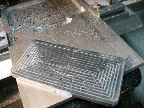
| .250" Aluminum has been resurfaced to .003" and here you see the degree lines being milled in 5 degree increments. | 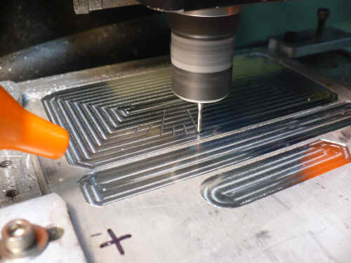 |
|
|
|
|
Sheetcam view of the DXF file telling the mill what to do next |
 |
|
|
|
|
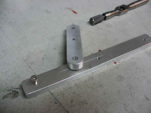
Lathe tool support guide on top - .500" x 2.375" x .250" Jig slide guide on the bottom - .500" x 5.00" x .250" All hardware used to assemble the jig is #4 - 40 |
|
|
|
|
|
The main plate 5.00" x 2.50" x .250" |
|
|
|
|
|
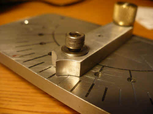
The bottom threaded hole lines up with the
series of holes in the main plate. I was concerned that the knurled knob
may not be secure enough so these holes could be used for a locating pin
to hold the angle perfectly in place while sharpening.
To make the pin, I used a #8 machine screw and turn down the end to .125" diameter x .125" long. A few turns of the screw locks everything in place. |

|
|
|
|
|
.I spray painted the surface before wet sanding but got a bit too anxious and when I started sanding, the paint came off. I'll try it again another day The center hole in the guide is in case I decided that I wanted to clamp the lathe tool in place. I may thread this and make a clamping plate. |
 |
|
|
|
| Here you can see how it slides along the store bought
angle stand.
Come back later as I may have added the extra features noted in the previous frame. |
 |
|
|
|
|
|
|
|
Updated: December 03, 2012 |
Design © David J Morrow 2012 |